Lathe CNC Hollow Spindle 5″ Spindle 27″ Swing SS-27 Series T
MEGABORE LG SERIES
LG Model
Lathes CNC Hollow Spindle LD Series
Lathe CNC Hollow Spindle 5″ Spindle 27″ Swing SS-27 Series T
Description
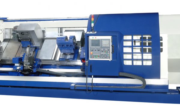
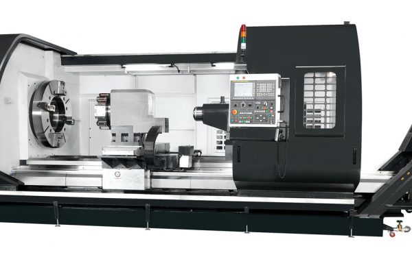
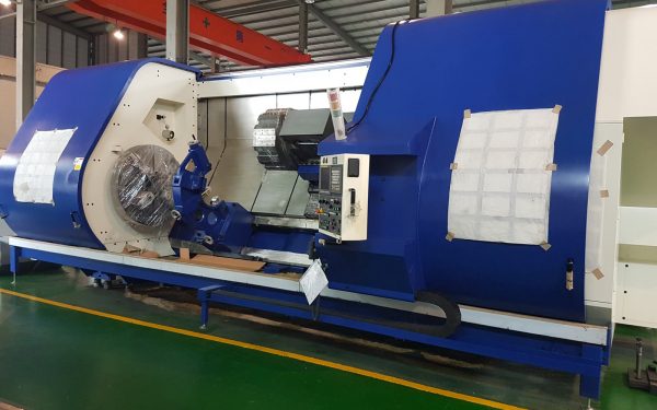
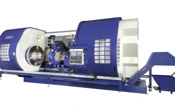
The Megabore SS27 T series has been designed for workshops who require larger than usual hollow spindle, without going to a large oil country lathe.
| ITEM | UNIT | SS-27(TS) | SS-27(TC) | SS-27(TY) |
| CAPACITY | ||||
| Centre height | mm (in.) | 505 (19.88) | ||
| Swing over bed | mm (in.) | 700 (27.55) | ||
| Swing over cross slide | mm (in.) | 570(22.44) | ||
| Max. Turning Diameter | mm (in.) | 680(26.77) | 570(22.44) | |
| Distance between centres | mm (in.) | 700(27.55) / 1200(47.24) / 1700(66.92) / 2200(86.61) / 2700(106.29) / 3200(125.98) | ||
| BED | ||||
| Width / Slant angle | mm (in.) / deg | 1270(50) / 45° | ||
| CARRIAGE | ||||
| Width of cross slide | mm (in.) | 400(15.74) | ||
| SPINDLE | ||||
| Spindle Nose | ASA | A2-11 | ||
| Chuck Size | inch | 15″ (V-215) STD /15″(N-215) OPT / 18″(V218) OPT / 18″(N-218) OPT | ||
| Spindle Bore | mm (in.) | Ø130mm (5.19) | ||
| Spindle speed | /min | 1800 | ||
| Bar Material Thruogh-hole Diameter | mm (in.) | Ø117(4.6) | ||
| TURRET | ||||
| Standard turret | Polygon Disc / VDI disc / BMT65 disc | |||
| No. of tool stations | V12 | |||
| Turning Tool Size | mm (in.) | 25 x 25 (0.98) | ||
| Boring Tool Size(max.) | mm (in.) | 40 (1.57) | ||
| Indexing Type | Servo | Servo | Servo | |
| Tool Driver system | STATIC | BMT65 | BMT65 | |
| Tool Holder Type | STATIC | DAEWOO | DAEWOO | |
| Tool Holder Type | SAUTER 0.5.440.220 | DUPLOMATIC DM-TR20 | DUPLOMATIC DM-TR20 | |
| Turret Servo Motor | KW | N/A | 5.5KW (α30/4000is) | |
| Tool To Tool Change Time (Neighboring Tools) | sec. | 0.3 | 0.3 | 0.3 |
| Tool To Tool Change Time (Opposite Change Tools) | sec. | 0.9 | 0.9 | 0.9 |
| TRAVEL | ||||
| X axis travel | mm (in.) | 330(12.99) | 290(11.41) | 280(11.02) |
| Z axis travel | mm (in.) | 700(27.55) / 1200(47.24) / 1700(66.92) / 2200(86.61) / 2700(106.29) / 3200(125.98) | ||
| Y axis travel | mm (in.) | N/A | N/A | ±75(2.95) |
| Cutting feed rate | mm(in.)/rev | |||
| RAPID TRAVEL | ||||
| X axis | M./min | 10 | 10 | 10 |
| Z axis | M./min | 6 | 6 | 6 |
| Y axis | M./min | N/A | N/A | 10 |
| Ballscrew diameter | mm (in.) | X axis : 50(1.96) ; Z axis : 63(2.48) ; Y axis : 40(1.57) | ||
| TAILSTOCK | ||||
| Tailstock travel | mm (in.) | 600(23.62) DBC=700(27.55) / 1100(43.3) DBC=1200(47.24) / 1600(62.99) DBC=1700(66.92) 2100(82.67) DBC=2200(86.61) / 2600(102.36) DBC=2700(106.29) / 3100(122.04) DBC=3200(125.98) |
||
| Quill diameter | mm (in.) | 115(4.52) | ||
| Quill travel | mm (in.) | 150(5.9) | ||
| Internal taper of quill | MT#6 | |||
| MOTOR | ||||
| Headstock oil refrigerator | ||||
| Main spindle | KW(HP) | 22KW (α22/7000i)-STD | ||
| Axis servo | KW(HP) | X axis : 4.5KW (α22/3000i) Z axis : 4.5KW (α22/3000i) Y axis : 4.5KW (α22/3000i) |
||
| Hydraulic tank | KW(HP) | |||
| Coolant pump | KW(HP) | |||
| Controller | FANUC 0i-TF series-STD ; FANUC 31i-B series / Other required-OPT. |
|||
Note :
(1) X and Z axes actual cutting diameter will change when equipped with different turrets.
(2) Specifications are subject to change without notice for improvement


